| Trash pumps and high pressure centrifugal pumps - How they do their work. For product information click on the links below for centrifugal pump, Diaphragm pump, Little Giant Pump or submersible pump |  |
|
|
|
| Trash pumps and high pressure centrifugal pumps - How they do their work. For product information click on the links below for centrifugal pump, Diaphragm pump, Little Giant Pump or submersible pump | |
|
|
|
|
The overwhelming majority of contractor pumps use centrifugal force to move water. All centrifugal pumps use an impeller and volute to create the partial vacuum and discharge pressure necessary to move water through the casing. The impeller and volute form the heart of the pump and help determine its flow, pressure and solid handling capability. An impeller is a rotating disk with a set of vanes coupled to the engine/motor shaft that produces centrifugal force within the pump casing. A volute is the stationary housing (in which the impeller rotates) that collects, discharges and recirculates water entering the pump. A diffuser is used on high pressure pumps and is similar to a volute but more compact in design. Many types of material can be used in their manufactire but cast iron is most commonly used for construction applications. In order for a centrifugal pump, or self priming, pump to attain its initial prime the casing must first be manually primed or filled with water. Afterwards, unless it is run dry or drained, a sufficient amount of water should remain in the pump to ensure quick priming the next time it is needed.  As the impeller churns the water (see figure above), it purges air from the casing creating an area of low pressure, or partial vacuum, at the eye (center) of the impeller. The weight of the atmosphere on the external body of water pushes water rapidly through the hose and pump casing toward the eye of the impeller. Centrifugal force created by the rotating impeller pushes water away from the eye, where pressure is lowest, to the vane tips where the pressure is highest. The velocity of the rotating vanes pressurizes the water forced through the volute and discharges it from the pump. Water passing through the pump brings with it solids and other abrasive material that will gradually wear down the impeller or volute. This wear can increase the distance between the impeller and the volute resulting in decreased flows, decreased heads and longer priming times. Periodic inspection and maintenance is necessary to keep pumps running like new. Another key component of the pump is its mechanical seal. This spring loaded component consists of two faces, one stationary and another rotating, and is located on the engine shaft between the impeller and the rear casing (see figure below). It is designed to prevent water from seeping into and damaging the engine. Pumps designed for work in harsh environments require a seal that is more abrasion resistant than pumps designed for regular household use.  Typically seals are cooled by water as it passes through the pump. If the pump is dry or has insufficient water for priming it could damage the mechanical seal. Oil-lubricated an occasionally grease-lubricated seals are available on some pumps that provide positive lubrication in the event that the pump is run without water. The seal is a common wear part that should be periodically inspected. Regardless of whether the application calls for a standard, high pressure, or trash every centrifugal pump lifts and discharges water in the same way. The following section will point out design differences between these pumps. Standard Centrifugal Pumpsthese pumps should only be used in clear water applications (agricultural, industrial, residential) as they have a limited solid handling capability of only 10% by volume. The impellers typically use a three-vane design (see figure below) and the volute is compact, preventing the passage of large solids. The rule of thumb is the pump will only pass spherical solids 1/4 the diameter of the suction inlet. 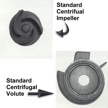 One advantage these pumps have over comparably sized trash models is their low initial cost. There are several reasons for this difference. Lower horsepower engines are utilized that are smaller in size and more fuel efficient. The mechanical seals, since they are not subjected to harsh working conditions, can be made of less costly material. Additionally, the casings are smaller and have fewer machined parts that when combined with the smaller engines make the pumps much lighter in weight. High Pressure Centrifugal PumpsTypically these pumps will discharge around 100 GPM and produce heads in excess of 240 feet. The pump may have a 2 inch suction port and up to three discharge ports of varying size for added versatility. The impellers used on these pumps are a closed design (see figure below) and not open like those used on other types of centrifugal pumps. Similarly the diffuser is more compact than a regular volute in order to generate the high discharge pressures. 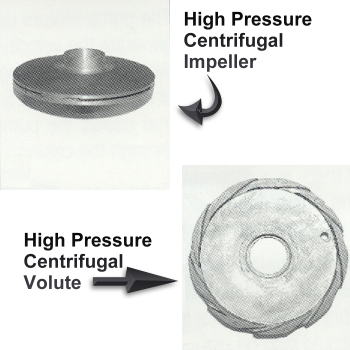 These pumps by design are not capable of handling any types of solids or even sandy water, Silt, sand or debris would almost immediately clog the pump if allowed to enter into the casing. Additionally, the impeller and diffuser may be made of aluminum rather than weather resistant cast iron since they are not subject to abrasive materials. It is recommended that a mesh net always be placed over the suction strainer if the pump is being used in dirty water. Trash Centrifugal PumpsThe rule of thumb is that a trash pump will generally handle spherical solids up to 1/2 the diameter of the suction inlet. Solids (sticks, stones and debris) flow through without cloggin making themideal for the water conditions typically found on job sites. Trash pumps handle up to 25% suspended solids by volume. Trash pumps offer another benefit in that they can be quickly and easily disassembled for service or inspection. While standard pumps require special tools that are not always available the inside of a trash pump gousing can usually be accessed with common tools. Customers occasionally ask why a trash pump costs more than standard centrifugal pumps. One big reason is that higher horsepower engines are neeed for trash pumps. The impeller is typically a cast iron two-vane design (see figure below) and a large volute is required to handle the higher volume of water and debris. The mechanical seal - like the impeller and volute - is selected for its abrasion resistance and more parts are machined for the casing. While there is a higher initial cost it must be noted that is is recovered through the reduced maintenance over the life of an often used pump. 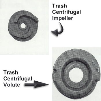 |